Timber’s performance changes with long term loading and variations in humidity and moisture. Changing the building environment can have a dramatic affect on timber components.
Alan Holmes
is a Chartered Building Surveyor and Managing Director of Building Surveyors, Architectural Technologists and On Construction Domestic Energy Assessors, Alan Holmes Building Surveying Services Ltd.
Abstract
A common problem is deflection in timber purlins and beams. However, sometimes things are not as straight forward as first thought. In this paper the author considers how the environment of a building can affect the performance of timber members.
Keywords:
Timber, purlin, bressemmer, ventilation, humidity, cupping, twisting, bowing, creep deflection.
Introduction
A local authority tenant had reported cracking in the timber purlin of the roof. The local council asked us to report on the adequacy of the roof structure. What seemed to be a simple deflection of purlin ended up questioning the changing environment in the roof space and the effect it has on timber members.
This article looks at the affect loading and changes in moisture content and relative humidity can have of timber in buildings.
Long Term Loading of Beams
A typical example of deterioration in timber affecting the strength of timber is the bressummer beam. This is probably the most common cause of failure with timber lintels. When a beam of whatever material is loaded an initial deflection occurs and with steel or concrete that is the end of the matter. However, timber under prolonged high stress will very gradually continue to deflect with the passing of years, a phenomenon known as creep deflection. The structural member most at risk is the beam, or bressummer, supporting the external wall and first-floor over a single-storey bay window and often the whole street of similar houses will exhibit the same pattern of stepped cracking above the bay window.
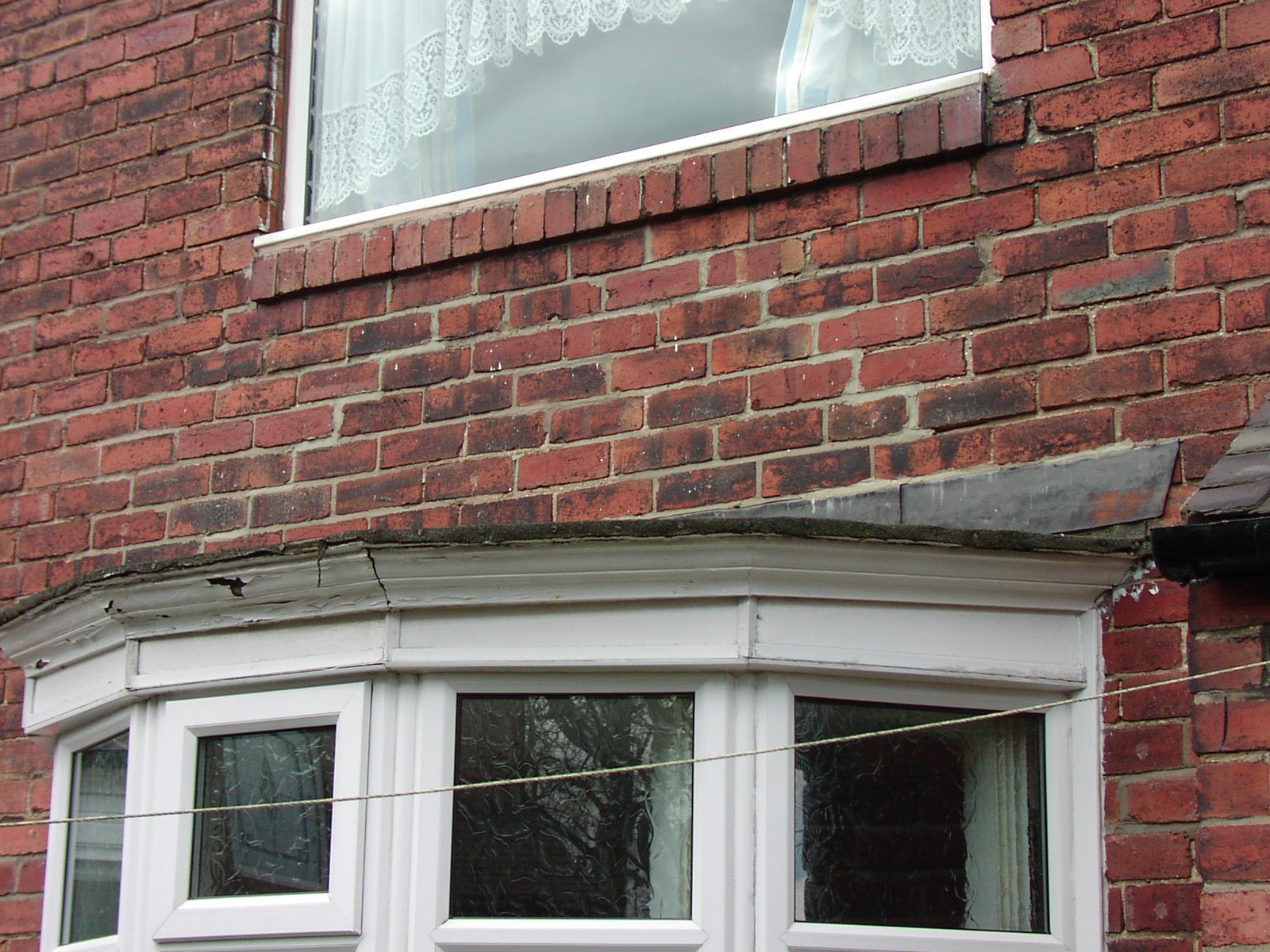
The beam or bressummer is normally made up of three floor joists with spacers between to make up the wall thickness, whilst the floor joists either go over the top and form the ceiling/roof to the bay or more commonly are tusk tenoned into the inside joist.
If the cracks are just caused by nothing more sinister than creep deflection and provided the bressummer is adequate in other respects then normally all that is needed is to rake out the cracked joints and repoint.
Water Ingress and the Risk of Fungal Decay
However, if the property is earlier than about 1920 and the bay has a flat roof it would almost certainly have been leaded. Sheet lead has a life of about 50 years after which deterioration occurs either by splitting dues to thermal stress or the formation of pin holes caused by corrosion or breakdown of small foreign particles in the original lead. This leads to water penetration which if neglected could lead to wet or dry rot in the bay roof timbers or the bressummer. If the lead has been replaced with felt is usually a sign that there has been water penetration in the past and it should be treated with suspicion.
Unfortunately it is not easy to check whether the bressummer has been affected by rot without extensive opening up unless there are obvious signs of say a dry rot fungus. The properties most at risk are houses built prior to 1920, with a flat roof over the bay that has had the original lead replaced. If in these circumstances the cracks are relatively recent and show on the inside as well as the outside of the wall it can be assumed that there is probably wet or more likely dry rot in the bressummer, in which case it must be removed and replaced with a steel beam.
Timber Shrinkage
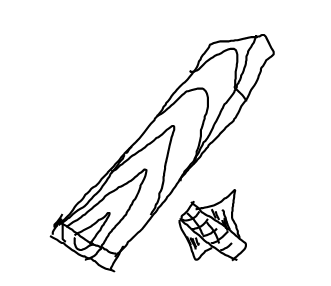
A common problem in properties is the shrinkage of timber shortly after construction with opening of joints in architraves and skirting and twisting and warping of timber doors. Another significant effect is shrinkage of timber following a flood. The photograph below show splitting in the staircase string painted after the property had suffered a severe flood following a burst water tank in the roof.
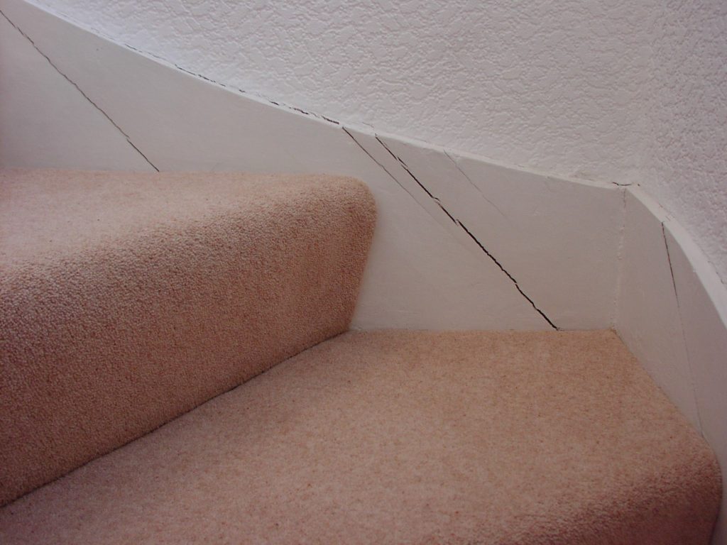
Our client believed that the property had fully dried, and carried out repairs and redecoration, 6 months later these cracks in the timber string of the staircase and opening joints in door architraves and skirting appeared and we were called to inspect structural movement. There is no structural movement, moisture contents in the timber were found to be 19% when tested with an electronic resistance moisture meter and the timber is continuing to dry.
Changing Humidity Levels
This brings us to our main story. Our client’s tenant had report significant cracking in the timber structure of their home. The splitting in timber had been diagnosed as structural movement due to loads from the roof. We were asked by the Local authority to inspect the cracking and structural movement and report on the cause and recommend repairs.
This was a very interesting case in where, the changes of ventilation in a roof void had affected the relative humidity and lead to volumetric changes in the timber members of the roof structure. The house was a typical local authority semi detached house with brick cavity walls supporting a twin pitched and hip end roof.
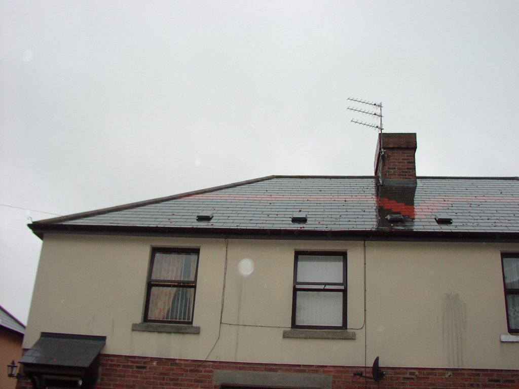
The original roof covering was asbestos cement tiles, the roof had been recovered with ‘Eternit’ type slate substitute tiles.
The roof has vent tiles in the external face above eaves level to provide cross ventilation. However, our internal inspection revealed that the vent tiles did not extend beyond the sarking felt and therefore they were not ventilating the roof space. There was no ridge ventilation.
The tiles are laid over a plastic ‘monarflex’ type sarking felt, which is impermeable and will not allow vapour evaporation. There was no evidence of condensation or water penetration in the roof void at the time of our inspection. The ventilation met the requirements of The Building Regulations 1991 as amended, Approved Document F2, The Building Standards (Scotland) Regulations 1990 – 1994 Part G where appropriate and BS 5250.
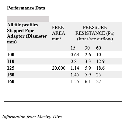
Ventilation to the Roof (extracts from Marley roofing web site)
The Ventilation Roof Tiles provide 20,000mm² free area of ventilation.
British Standard 5250, the Code of Practice for the Control of Condensation in Buildings, and the Building Regulations Approved Document F2, have for many years recommended that the way to control the build up of condensation in roofs is through the use of ventilation. While systems that avoid the use of ventilation have been marketed by some companies, ventilation is still the most popular system for complying with Building Regulation F2.
The basic requirements for ventilating a traditional cold loft space are that air should enter the loft at the lowest point on one side of the roof and exit on the opposite side of the roof. Water vapour rises up through quilt or fibrous insulation, and meets the air in the loft, where some of the moisture is absorbed – the quantity depends on the air temperature.
Warm air can absorb more water vapour than cold air. If the air layer directly above the insulation is constantly changing it stands a good chance of absorbing most or all of the water vapour and take it outside. The warmer the air in the rooms below the insulation the higher the amount of moisture that can be absorbed. The cooler the loft the less moisture that can be held before condensation forms. Consequently if air leakage into the loft is full of moisture then the risk of condensation forming in the loft increases. This can be reduced if a vapour check layer is introduced below the insulation such as foil backed plasterboard, or a layer of polythene, along with sealed holes and openings.
Over time it is almost impossible to keep out all water vapour from the loft. During cold weather the risk of condensation forming is greater. Air flow through the loft can discourage condensation.
Most days we have a slight breeze causing a small positive wind pressure on one side of a roof and a small negative pressure on the opposite side. This pressure difference can drive a flow of air through the loft provided there are suitable air gaps on each side of the roof linked to the loft space. But if there is no wind, then there will be no positive or negative pressure to drive the air through the loft.
Therefore, air that leaks through the insulation will be warmer than the air in the loft and will try and rise to the top of the roof. It will become trapped under the ridge and start to cool, where it will form condensation on cold surfaces. If there was a vent at the ridge, the air would be carried outside and cease to be a problem.
Air should never be allowed to enter at a ridge, only leave. It is for this reason that most roof tile manufacturers will recommend eaves to ridge ventilation as it will cope with both the wind and no wind situations. (Eaves to eaves ventilation is designed to work with a slight breeze.)
The size of the grills through which air enters and leaves a roof is prescribed as a continuous 10mm gap at eaves or low level, with a continuous 5mm gap at ridge or high level. These figures are a compromise. On calm days they are too small, on very windy days they are too large. Temperature and moisture levels constantly change, making a precise level of ventilation almost impossible to achieve. Although over time more water vapour should leave the loft than enters it from below.
We noted that, following roof recovering:
- Ventilation tiles did not penetrate the sarking and therefore did not ventilate the roof void.
- There were a few very large vent tiles or grills rather than a continuous slot or grill. The larger the vent or grill, the greater the distance between the vents or grills resulting in a massive localised air flow close to the vent and little or no air flow as you move away from the vents
- Vents were directly in line with vents on the opposite side. This can create a wind tunnel across the roof between the large vents and no air movement as little as 600mm away.
Marley roofing guidelines state that the worst combination is four large vent tiles positioned at mid span on each face of a pyramid roof in an exposed location. This is similar to the situation at the house inspected, except the tile vents did not penetrate the sarking.
Roof Structure
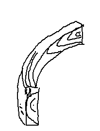
The roof structure itself comprised 50mm x 75mm common rafters at 425mm centres supported on a single 65mm x 200mm purlin to each roof slope and hip rafters. The purlins were supported by a single truss; with a tie beam, collar beam spanning between the front and rear purlins fixed to the common rafters, and a strut notched over the roof purlin. The strut resisting inward deflection but not preventing downslope deflection.
In addition there was a half truss spanning between the main truss and the side wall with a tie beam and single strut but no collar beam.
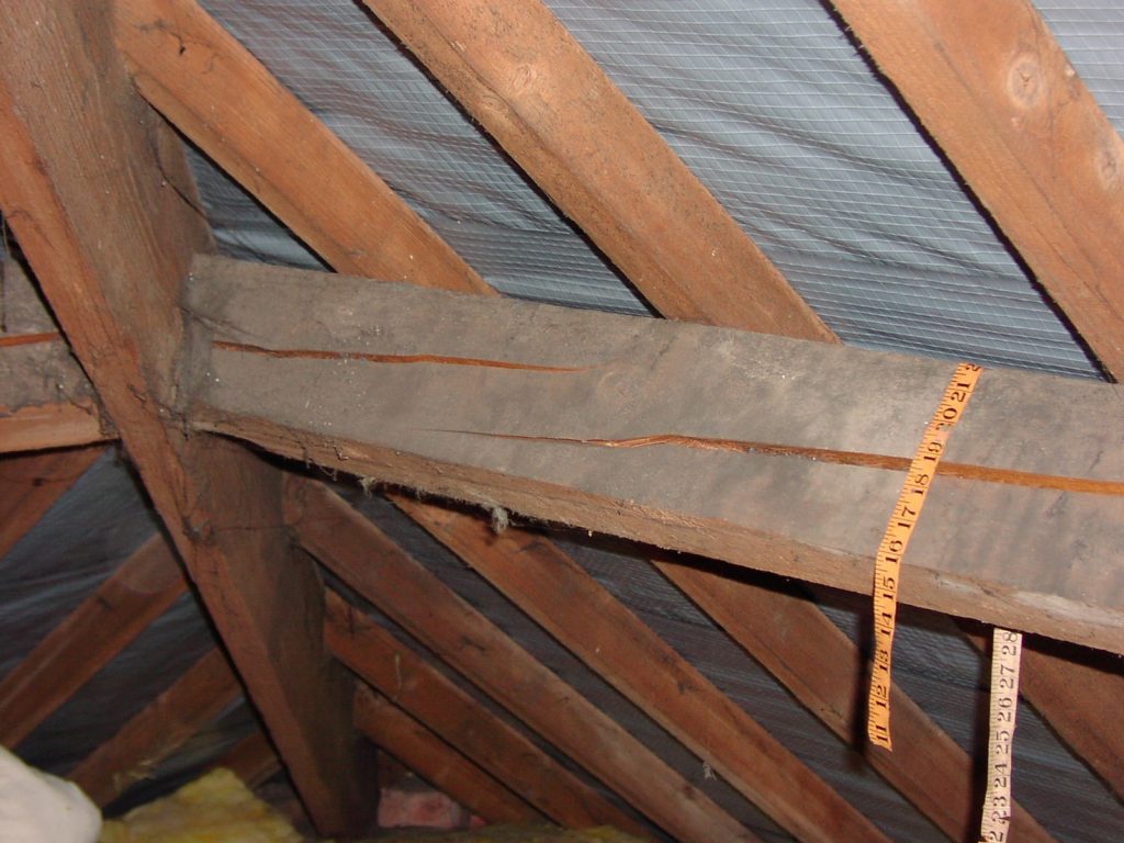
Our inspection revealed up to 12mm wide shakes along the roof purlins on all slopes.
There was a broken common rafter on the rear roof slope.
By inspection, there was no evidence of distress in the purlins; however, it is unlikely that the purlins could be justified using current engineering codes. Apart from the broken rafter which probably occurred during re-roofing no distress in the roof slopes was evident.
Stress Grading
Calculations show that the roof purlins do not comply with current regulations. Structural design criteria for wood components assume that the wood has adequate strength, but this will depend upon the species and grading of the timber. In BS5268:Part 2 Code of practice for permissible stress design, material and workmanship, design flexibility is allowed by relating design criteria to strength class, e.g SC3, GS or M50 grades. GS represents General Structural Grade determined by visual stress grading and M50 is the equivalent grade determined by machine stress grading. The first feature in visual stress grading is to determine that the wood has the correct cross section, i.e this has not been altered by sawing or machining. The presence of wane, which is the curved edge of the log along the arris of wood also affects the cross section.
Structural timbers (as required for bridges) are stress graded according to the proportion of defects in the sawn section. For softwoods the gradings are divided into GS (General Structural Grade), and SS (Special Structural Grade). Where the grading has been done by machine, the gradings are MGS or MSS. The timber is further defined by species eg Grade GS Scots pine. Hardwoods have a single grading HS (Hardwood Structural). Where the selection of a timber species is not important, timber may be specified by its SC (Strength Classification). For further details see British Standard 4978 for softwood, and British Standard 5756 for hardwood.
Softwoods most commonly used for bridges are Douglas fir, larch and Scots pine, either imported or home grown, and meeting strength classification SC3 and SC4 and higher. Timbers to strength classification SC1 and SC2 are unlikely to be useful for footbridges. Hardwoods used are mostly imported, such as Keruing and Ekki.
As a result of amendments to BS 4978 and BS 5268, there are new ‘marks’ for structural timber graded from the 1 March 1995.
The amendments require all structural softwood specified for dry covered applications (rafters, joists and studwork) and having a thickness of less than 100mm to have been dried to a moisture content of 20% or less at the time of stress grading. The grading ‘mark’ must include ‘DRY’ or ‘KD’ (Kiln Dried).
However, the most important factor in stress grading is the knot area ratio. The ratio of knot area projected on a cross section relative the total area of wood, determines the integrity of the cross section of timber. Splits, fissures and resin pockets must also be taken into account for grading. Unlimited fissures are permitted if they are less than one half the thickness of the piece. If they are greater than half the thickness but less than the whole thickness, their length should not exceed 900mm for GS grade or 600mm for SS grade, or one quarter of the length of the piece, whichever is the lesser.
The grading also considers growth rate rings and there should not be less than four rings per 25mm, the slope of the grain should be less than 1 in 6 for GS grades and 1 in 10 for SS grades. Finally, the wood should not be excessively distorted. Within a 3m length the bow should not exceed one half of the thickness, spring should not exceed 15mm and twist should not exceed 1mm per 25mm width. The depth of cupping should not exceed one twenty fifth of the width.
Splitting in Roof Members
The existing timber with the shakes, splits and fissures exceeding 900mm in length and extending over half of the thickness of the timber combined with the slope of the grain, would have a very poor stress grade. Please note – the tenant had placed the tape measure over the purlin, it is not generally used as a surveying tool, but does emphasise the extent of cracking.
When an old timber roof is recovered, it can be subjected to substantially higher loads from the new tiles or slates than from the original ones. The roof construction that has performed satisfactorily before recovering may show signs of dishing or sagging of the ridge and may collapse under a heavy snow load. This is particularly relevant when a roof of Welsh slates is replaced with plain clay tiles or concrete interlocking tiles as the following self-weights demonstrate:
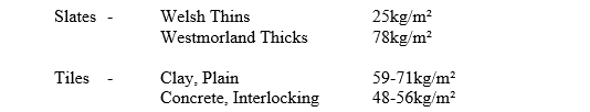
It can be seen that the dead load can easily be doubled when changing from say Welsh slates to concrete interlocking tiles or clay tiles.
Overloading will normally manifest itself in sagging purlins and sometimes roof spread.
However, in this instance the existing roof covering has been replaced with a new roof covering of similar weight. The loads on the purlins have not been increased and we do not consider the shakes in the purlins to be caused by deflection or shear stresses.
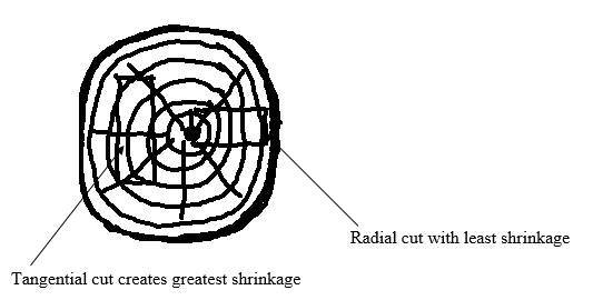
The properties of wood are profoundly influenced by the presence of water. Freshly felled timber is often described as green and has a very high moisture content varying typically between 60-200%. The loss of bound moisture from the cell space and eventually the cell walls results in shrinkage and progressive change in the physical properties. In addition, the amount of bound water remaining in the wood is approximately proportional to the relative humidity of the surrounding atmosphere; wood is hygroscopic and will gain or lose water with changes in atmospheric humidity, and these changes result in swelling and shrinkage. Swelling or shrinkage with changes in moisture content is known as movement. In the longitudinal direction the movement is generally very low, only about 0.1% for a 12% change of moisture content. In contracts, the movement in the radial direction for the same moisture content is about 3 to 5% and in the tangential direction 5% to 15%.
Warping is the general term for distortions on drying and takes several forms:
- Cupping is warping across the grain or width of the board and arises in flat sawn boards because the outer zones of the trunk, particularly the sap wood, shrinking to a greater extent than the inner zones, giving a planoconvex surface on the outer side of the board or timber section relative the trunk.
- Twisting arises in timber due to the presence of spiral grain.
- Bowing is longitudinal curvature arising perpendicular to the surface, usually occurring as sagging while stacked during drying or from loading and creep deflection.
- Spring or crooking is longitudinal curvature within the pane of the board caused by tensions within the original tree.
When the roof was recovered over an impervious sarking the ventilation to the roof was reduced. The ventilation tiles installed have been shown to be poorly positioned, and as the ventilation tiles do not pass the impermeable sarking are totally ineffective. Insulation over the ceiling was increased and the relative humidity in the roof space was drastically altered.
In turn this has affected the hygroscopic timber and caused shrinkage, cupping and splitting.
The timber’s stress grading will have been affected and what was originally a suitable stress grade for the roof purlins is now significantly lower due to the splitting in the purlin.
It is imperative that the relative humidity in the roof void be adjusted by extending the roof tile vents through the sarking to ventilate the roof space and de-creasing the relative humidity.
By inspection, we are satisfied that the roof structure is not suffering from any major distress, however to improve the integrity of the split purlins we recommended that the upper face be over clad with 12mm plywood. In plywood, the grain runs horizontally in both directions within the plane of the board, and it is equally strong in both directions. The adhesives in the plywood have been developed to resist very high stresses. The plywood should be cut, in full lengths, to cover the full face of the purlin and glued and screwed at 150mm centres, 15mm from both the top and bottom edges of the purlin.
Recommended Repair
We specified that 2400mm 12mm thick marine plywood sheets should be cut along their length, to cover the full face of the purlin. Glued and screwed at 150mm centres, 15mm from both the top and bottom edges of the purlin the plywood to the purlin.
Extend vent tiles through sarking to ventilate the roof space.
Bolt SC4 50mm x 75mm rafter along side broken rafter with M12 bolts and toothplate connecters at 600mm centres.
Summary
This article is not written to detail a single survey I carried out. Hopefully, this article helps us consider that cracks in timber can be miss-identified and are not always evidence of structural movement due to loading. That the ventilation and control of unexposed voids (roof spaces, sub floor voids) is critical and should be correctly specified when recovering roofs. When a timber is stress graded, it is graded on its condition at that time. Subsequent moisture variation, twisting, cupping, fungal decay and insect attack will affect the stress grading. Where a structural timber was adequate in design it may no longer be adequate after use.
Alan Holmes DipSurv, MRICS, MCIOB, MaPS.
References
R M Higgins Fact sheets – 2. Recovering Old Timber Roofs 6.Structural Timbers and 13d. Sagging Lintels
Marley roofing guidelines – Web site
The Building Regulations Approved Document F2
BS 5250 the Code of practice for the control of ventilation in buildings.
Defects and Deterioration in Buildings – Author, Barry A Richardson published by E & F N Spon