Received (in revised form): 5th May, 2005
Alan Holmes is a chartered building surveyor and the Managing Director of building surveyors and asset managers, Elliott Holmes Johnson Ltd. He has specialised in building defects of residential properties for 14 years. Elliott Holmes Johnson is a firm of independent consultants which advises Registered Social Landlords on asset management strategies as well as carrying out single surveys for home purchasers.
Abstract
Specialising in surveys of domestic residential properties and, in
particular, clients with large housing stocks such as local
authorities, the author’s company is finding an increasing number
of defects in the housing stock built in the 1960s and 1970s. In this
paper, the author considers how these inherent defects are
exacerbated by the changing climate such as the increase in wind
speed and frequency of gale force winds.
INTRODUCTION
The author’s company was asked by a local council to survey a number of
its properties, which were suffering a lean of the gable wall of bungalows.
It was discovered that the gables were leaning due to roof trusses lying
against the gable peak.
The properties comprised 56 semi-detached and terraced, single-storey
bungalows and two semi-detached, two-storey houses, all built in 1976.
The site sloped gently from south to north. The estate was exposed to the
wind from the east, and fairly sheltered in all other elevations.
A plumb survey was carried out on every bungalow gable wall and
peak. A visual examination was carried out on the peaks to both houses.
An internal examination of the roof space and trusses was carried out in at
least one bungalow in each block. Only one of the bungalows, inspected
internally, had the close centred trusses braced, one further bungalow had
ridge bracing only. There were no restraint straps in any of the properties.
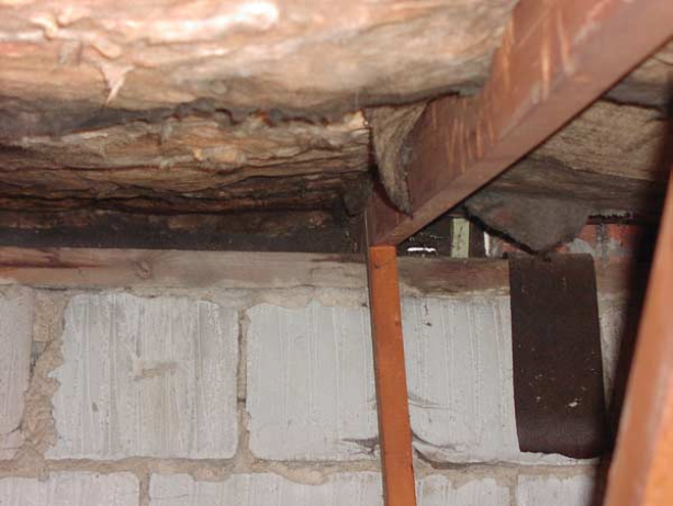
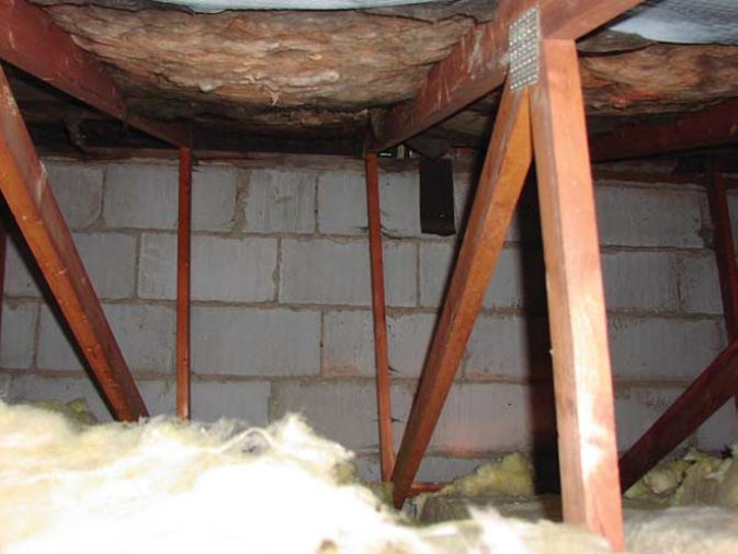
The plumb survey revealed that the gable walls up to the peak were in
general plumb. The peaks, however, had varying degrees of ‘leaning’, as
illustrated in Figures 1 and 2. They varied from plumb to a 175mm
outward lean.
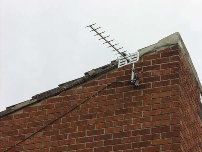
The interlocking concrete tile roof cladding, in the main, had slid
over the gable and party walls in the direction of the truss displacement
(see Figure 3). In most cases it had slid over the peaks without causing
damage.
VULNERABILITY OF THE PROPERTIES DUE TO FORM OF CONSTRUCTION AND EXPOSURE
The bungalows and houses had been traditionally constructed. The estate
was exposed to easterly winds. There was no evidence of deleterious
materials in the construction. Vulnerability to damage was dependent
upon the lack of bracing and absence of restraint straps in the close centred roof truss system and exposure to high winds.
There are a variety of different methods of assessing the exposure of a
site, often resulting in disagreement as to whether a site is ‘exposed’ or not.
The mathematical calculation of site exposure, however, is a well documented science in comparison with the more vague nature of
guidance on how to detail a building properly to reflect such exposure.
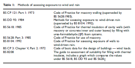
Alternative methods of assessing exposure to wind and rain are
included in the British Standards, Codes of Practice and BSI Drafts for
Development detailed in Table 1. All the methods listed in Table 1 (with
the exception of CP 3) are developments of the original Driving Rain
Index developed by Lacy (1976). The three original bands (sheltered,
moderate and severe) have been expanded to five, with overlaps between
them. Many of the local features mentioned but not taken into account in
the original method have now been included (as modification factors).
Each method has its merits. The most accurate methods make use of
recent meteorological research, which is now considered to be the best
indication of likely water penetration.
The Building Research Establishment (BRE) publications were
superseded by the British Standard Draft for Development DD 93: 1984,
‘Methods for assessing exposure to wind-driven rain’, and then by BS
8104: 1992, ‘Code of practice for assessing exposure of walls to winddriven
rain.’
THE TAU ASSESSMENT
It was necessary for the system of exposure assessment used in the
report to be easily understood even with limited information available
on local topography. Taking account of local driving rain, general
topography, building height and design features, the assessment method
needed to relate a calculated exposure rating to particular forms of
construction.
CP 121 has been superseded and therefore the options available were
either BS 8104 (which closely follows BS DD 93) or BS 5618. However,
we chose to use the tabular method described in BS 6399: Part 2: 1997.
It also offers a readily assessed rating basis without requiring
unreasonably detailed submissions of information. It takes into account
the major factors affecting the risk of water penetration through external
masonry walls. The author concluded that the most exposed wall of the
building determines the construction for the whole building, since it is rare
for detailing to be varied from wall to wall according to orientation,
nearby trees and similar protective features.
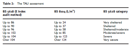
For guidance, the ratings used by the Technical Audit Unit (TAU) of
Housing Association Property Mutual for each category are shown in
Table 2. The exposure categories given in each British Standard overlap,
and therefore the top value within each category is taken as the divider
between ranges for the purposes of the audit. This means that a very
optimistic view of the exposure rating is taken by the TAU.
Once exposure had been determined, the consultants had to consider
how secure the roof was and they referred to the roofing manufacturer’s
(Stanley) guidelines and specification. The BRE rain index and exposure
map defines Stanley as having moderate to high exposure. In 1971 the
Building Research Station published Digest No.127, ‘An Index of
Exposure to Driving Rain’ (Lacy, 1971), based on work done at the BRE
during the 1960s. A further BRE report entitled: ‘Driving-rain Index:
Annual Mean Driving-rain Index in the United Kingdom with Proposed
Revised Rules for Assessing Local Exposure’ was published in 1976
(Lacy, 1976). A wind load calculation in accordance with BS 6399: Part 2:
1997 indicated a 22.18kN/m2 wind loading on the exposed west face
at upper eaves level. The circumstances of this construction were such
that the collapse of some of the bungalow peaks was imminent and all
others had the capability to become unstable.
STRUCTURAL PROVISION IN THE ROOF STRUCTURES
The roof structures included ‘trussed rafter’ type frames. These were
lightweight and closely spaced. They are a more economical system than
the traditional method of using heavy trusses, purlins and rafters.
Roofs constructed in new houses nowadays are universally built with
lightweight trussed rafters normally at 600mm (2-inch) centres. They are
fabricated from 38mm thick timber members fastened together in one
plane with metal connectors. The trussed rafters therefore provide support
for the tiling battens and the ceilings without the necessity of providing
separate ceiling joists, purlins or ridgeboard (see Figure 4).
The trusses are fabricated from high-grade timber under factory
conditions using specialised equipment, while the design is based on the
results of extensive research and testing. It should be emphasised that
trussed rafters are engineered components and satisfactory performance
can be ensured only by adopting correct erection procedures and fixing on
site under competent supervision. Trussed rafters normally span between
external load-bearing walls without the need for internal supporting walls,
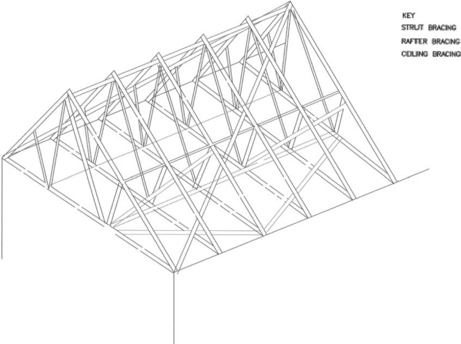
but adequate bracing of the whole roof and satisfactory connections to the
supporting structure are essential to ensure overall stability (see Figure 5).
While a trussed rafter roof is economical and cost effective it does have
its limitations. It is designed to the limits of the British Standards which,
while providing an adequate degree of safety, does not allow for any
increase in load over and above that for which it was designed. The loft
space, for instance, can be used only for light storage which should be
placed on boarding supported on the ceiling ties and not on the plasterboard ceiling. Supports for water tanks are engineered into the structure. The ‘forest’ of timber within the loft space discourages any ideas for a ‘loft conversion’. High levels of insulation above the ceiling create a ‘cold’ roof
in winter which can cause condensation unless a vapour barrier is
incorporated at ceiling level and ventilation is provided at eaves level
(this is particularly relevant for houses built before the introduction of the
1985 Building Regulations). Cold water pipes can freeze unless they are
well insulated, all water pipes should be kept out of the loft space.
One of the essential requirements when erecting on site is to provide
temporary bracing across the trusses to prevent a domino type of collapse.
This is normally incorporated in the permanent bracing, which ensures
that wind forces do not impair the stability of the roof, and is particularly
important on gable-ended roofs (as opposed to a hip-ended roof). Not
only must the roof structure be stable under wind loads, but the gable ends
must be prevented from being blown in under a positive wind pressure
or being sucked out under a negative wind pressure.
Wind bracing is normally provided, first, by introducing diagonal
bracing to the underside of the rafter members on either side, ensuring that
the bracing is either continuous or lapped across two adjacent trusses;
secondly, by diagonal bracing on top of the ceiling ties from end to end (or
from gable wall to party wall); and finally, by longitudinal bracing at the
ridge and at ceiling tie level ensuring that it fits tight against the gable
wall. The bracing timbers are normally 100mm £ 25mm and should be
fastened to each truss with two 75mm wire nails. These measures
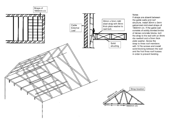
generally will accommodate all wind forces on the roof and positive wind pressure on the gable. To prevent the gable ends being sucked out under
a negative wind pressure the inner leaf must be tied to the first two
trusses with 30mm £ 5mm galvanised steel straps with timber noggin
strutting between the trusses.
A shortfall of structural provision with respect to the strapping of the
party and gable walls was found at the subject properties. Some limited
works intended to rectify this shortfall had been carried out by providing
varying amounts of bracing and props. Galvanised steel straps tying the
gable and party walls to the truss ties, and at rafter level, were absent in all
the properties surveyed. The shortfall of structural provision resulted in
some of the movement in the gable peaks and internal ceilings. At the time
of construction, diagonal bracing was not installed to tie the roof trusses
together.
OPINION ON CAUSES OF DAMAGE
The roofs were unstable due to a combination of causes, which are listed
below in what was considered to be the descending order of importance.
– Loading on the gable peak due to the ‘shunting’ effect of the leaning
roof trusses.
– A 22.18kN/m2 wind loading in exposed elevations.
– Shortfall or no provision of strapping of gable and party walls with the
roof trusses.
– Inadequate fixing of the roof structure to the external walls and no
provision of bracing to the roof trusses.
– Inadequate uplift restraint of the roof due to no provision of strapping of
the front and rear external walls with the roof trusses.
– Any roof with more than sheltered exposure to wind.
Some of the damage within the property ceilings and gable peaks was
likely to have been caused by a combination of the causes listed above.
RECOMMENDATIONS
- Galvanised steel straps should be installed to tie the trusses to the gable and party walls.
- Diagonal roof bracing should be installed to tie the roof trusses together.
- Additional fixings should be installed to hold down the roof trusses to the front and rear.
- Cracks in the ceilings should be cut out and filled using a proprietary filler.
- External cracks in the brickwork should be cut back and re-pointed.
COMPLIANCE WITH BUILDING REGULATIONS AND BRITISH STANDARDS
In addition, the Council wanted to know if the trusses had been erected in
accordance with legislation and Codes of Practice in place at the time.
Given that the properties were constructed during 1976, the following
regulations and British Standards were applicable.
– The Building Regulations 1965
– The Building Regulations 1976 (coming into operation on 31st January,
1977)
– CP 112: Part 2: 1971, ‘The Structural Use of Timber’
– CP 112: Part 3: 1973, ‘The Structural Use of Timber: Trussed Rafters
for Roofs of Dwellings’, September
– CP 111: Part 2: 1970, ‘Structural Recommendations for Loadbearing
Walls’
– CP 121: Part 1: 1973, ‘Brick and Block Masonry’
– Code of Practice for Walling.
The Building Regulations
Section D8 of the 1976 Regulations, ‘Structure Above Foundations’,
states:
‘The structure of a building above the foundations shall safely sustain and transmit to the foundations the combined dead load, imposed load and wind load without such deflection or deformation as will impair the stability of, or cause damage to, the whole or any part of the building.’
D12 Deemed to Satisfy Provisions for Structural Work of
Timber
‘The requirement of regulation D8 shall be deemed to be satisfied as to any structural work of timber if:
a. The work complies with CP 112: Part 2: 1971
or
b. In the case of work which:
i) consists of a floor, ceiling or roof of a house which has not more than three
storeys and is intended to be occupied by one family only;
and
ii) includes any timber member within the meaning of Schedule 6, that member complies with the rules contained in that Schedule and the work in all other respects complies with CP 112: Part 2: 1971; or
c. In the case of work which consists of a roof of trussed rafter construction, the work complies with CP 112: Part 3: 1973.’
Deemed-to-Satisfy Provisions for Structural Work of Bricks, Blocks or Plain Concrete
‘The requirements or regulation D8 shall be deemed to be satisfied as to any
structural work of bricks or plain concrete if:
a. The work complies with CP 111: Part 2: 1970; or
b. In the case of work comprising a wall constructed of bricks or blocks to which Schedule 7 applies, the thickness of such wall is determined in accordance with the rules of that Schedule and the work in all other respects complies with CP 121: Part 1: 1973.’
CP 112: Part 3: ‘Trussed Rafters for Roofs of Dwellings’
The relevant sections of this design guide are those given in Clause 5.6,
‘Permanent Bracing’, which are reprinted here as follows.
‘Consideration should also be given to the need to provide permanent lateral bracing to the roof. Where walls are of insufficient strength to provide resistance to the lateral forces acting on the roof, lateral bracing of the trussed rafters should be provided independent of the walls. This should take the form of a system of members nailed to the underside of each rafter and sloping diagonally from ridge to eaves and spanning at least four trusses at each end of the roof. Where the walls are capable of providing lateral resistance they may be used as fixing points for the lateral bracing to trussed rafters. This could be done by positioning trussed rafters hard up against the walls and securing the tiling battens to the walls by positive fixings. Alternatively, longitudinal battens nailed to the underside of each trussed rafter and built into or fixed to the walls at each end of the roof would also be satisfactory.’
CP 121: Part 1: ‘Walling: Bricks and Block Masonry’
The relevant sections of the design guide are those given in Clause
3.2.2.2.2, ‘Walls with Edge Restraints’:
‘Generally, non-loadbearing walls which are subject to wind loads, should be designed on engineering principles. Nevertheless, certain rectangular external walls (see Fig. 22), in buildings up to and including four storeys high, may be proportioned in accordance with the recommendations of Table 2.1, depending upon the exposure zone given in Fig. 27 for the location of the building concerned.’
and
‘The maximum area of a wall, meeting with the requirements of this clause, should be limited to the values given in Table 2.1 depending upon the exposure zone and the edge support conditions which may be fixed or pinned.’
Conclusion on compliance with Building Regulations
and British Standards
The gable wall to the subject properties did not comply with the
requirements of CP 121: Part 1, in that the area of the wall was greater
than that allowed within the Code requirements, without the wall being
securely fastened to the first floor joists and the truss ties. The roof trusses
were not braced in accordance with the requirements of CP 112: Part 3
for one of the following reasons.
– No diagonal bracing had been installed.
– Although the tiling battens had been fixed to the gable wall in
accordance with the requirements of the Code of Practice, the gable
wall was incapable of providing lateral resistance to the trussed
rafters, because the truss ties were not adequately secured to the
gable wall.
CONCLUSION
Trussed rafters were first introduced in the mid-1960s. At first, the
somewhat flimsy nature of the trusses compared with the traditional truss and purlin system was treated with a degree of scepticism by the building
industry and the construction and erection was not regulated until 1973
when the first British Standards appeared. Up until then the significance of
wind bracing was not always fully appreciated and any property with a
trussed rafter roof built before, say, 1975 could be suspect and should be
checked out by a qualified structural engineer. Fortunately, remedial work
as a result of inadequate bracing is not normally expensive.
With the increasing wind loads there is an increased risk of unbraced
and unstrapped trusses ‘lozenging’, causing internal cracking to ceilings
and, in turn, causing structural instability of gable peaks. In addition,
trusses installed without uplift straps are also susceptible to lifting,
causing significant structural damage at ceiling-to-wall junctions and
lifting lintels.
References
(1970) Structural Recommendations for Loadbearing Walls, CP 111: Part 2.
(1971) The Structural Use of Timber, CP 112: Part 2.
(1973) Brick and Block Masonry, CP 121: Part 1.
(1973) The Structural Use of Timber: Trussed Rafters for Roofs of Dwellings, CP 112: Part 3, September.
(1984) Method for Assessing Exposure to Wind-driven Rain, BS DD 93.
(1985) Code of Practice for Thermal Insulation of Cavity Walls, BS 5618.
(1985) Code of Practice for Use of Masonry, BS 5628: Part 3.
(1992) Code of Practice for Assessing Exposure of Walls to Wind-driven Rain, BS 8104.
(1997) BS 6399: Part 2.
Bracing trussed rafter roofs — TRADA, BS 5268: Part 3.
Lacy, R.E. (1971) An Index of Exposure to Driving Rain. Digest No.127, Building Research Station.
Lacy, R.E. (1976) Driving-rain Index: Annual Mean Driving-rain Index in the United Kingdom with Proposed Revised Rules for Assessing Local Exposure, HMSO, London, UK.
TAU Assessment by Housing Association Property Mutual.
Download and Read the Full Paper