Alan Holmes DipSurv, MRICS, MCIAT Is a chartered Building Surveyor, specialising in building defect pathology. Alan is managing director at Alan Holmes Building Surveying Services Ltd, a firm specialising in Level 2 and Level 3 residential surveys.
Abstract
I have read many books and articles on surveying and building defects and in general they describe specific defects and discuss them. I have had to follow too many valuation or homebuyers surveyors’ reports and write structural reports on specific defects when the cause of the minor cracking or dampness was obvious and clear.
The approach to defects analysis is generally incorrect. It evolves around finding a defect and then the surveyor seeks cause, or side steps the issues and asks for a ‘specialist report’.
Surveyors (at all levels) need to be able to identify the age of buildings, their construction method and materials, what alteration have been carried out to and make assumptions on their previous use. Starting with this understanding of the building the book will then identify ‘typical’ defects in a variety of different residential buildings. From this understanding, form a hypothesis as to the cause of the specific defects, and to set up experiments to prove or disprove the hypothesis and recommend suitable repairs.
In this article, I propose to look at defects in a different manner and use a case study to explain the philosophy. First, by looking at the property with a holistic approach. Understand the construction, identify what can go wrong and why and then find these defects. Set up experiments to prove or disprove the hypothesis and use this ‘outwards in’ approach to defects analysis.
Introduction
The purpose of this Article is to explain the holistic approach to surveying. Surveyors, whether it is defects analysis or insurance perils investigations, should be warned against identifying a specific defect (effect) and then trying to find the cause. Even if this cause occurred a long time earlier. We need to start with a much more general view and understand how a property is constructed. To understand how a property is constructed we need to know the period that property was built, how it was built during that period and what are the common defects associated with that form of construction. We need to understand the needs of the occupiers and the owners and to understand what is often a defect to us may be less of a defect to the owner. We need to adopt the holistic approach, considering all our options as we approach the property, as we carry out the survey, as we take notes. Identifying a leaking gutter and water staining on the front elevation brickwork should alert us to the possibilities of internal dampness and in turn possible fungal decay associated with the areas of water penetration.
Throughout my years of surveying, I have followed numerous surveyors’ reports to provide the client with a diagnosis for a specific defect or in some cases numerous specific defects. It is always alarming if the surveyor has misidentified or failed to observe a significant, sometimes obvious, defect.
When the surveyor identifies a defect, their diagnosis is often to suggest that the purchaser obtains additional surveys from timber treatment experts, damp proofing treatment experts, wall tie remedial contractors or structural engineers, to carry out further investigations. This can often leave the purchaser feeling short changed as when they employ a chartered surveyor, what they usually expect is a conclusive report.
The valuation survey carried out by most lenders, considers the dwellings with a view to “value” rather than “condition”.
In any simple Level 1 or Level 2 survey, the surveyor has to have the skill and the knowledge to identify specific defects. They must have a methodology when carrying out an inspection. Consistency of such inspections is essential and whilst the method of carrying out the inspection is flexible; it is recommended that the surveyor carries out the same procedure for each inspection or survey. This rehearsed methodology assists the surveyor in ensuring that the surveyor identifies all the elements of a building, the surveyor does not overlook a significant component or defect. Judge Phillips, in Cross v Mortimer, said “We are convinced that the same level of expertise is required from the surveyor in carrying out a home buyer’s report and valuation (HBV) as that for a structural survey.” The same guidance will apply to a Level 1 survey.
A good starting point for the methodology of building surveying is the Royal Institution of Chartered Surveyors professional standards and guidance, UK Home survey standard 1st edition, November 2019. The guidance notes recommend the building surveyor inspects, considers and discusses constructional principles and applies an overall assessment, taking into account the likely scale of future maintenance.
Each surveyor may have their own preferred surveying method. I prefer to survey the external elements first, to start on the front elevation right corner, working clockwise round the building. Internally from the ground floor to upper floors and finally finishing in the roof space. However, there is more to the survey than just the building itself. Wherever possible (time constraints sometimes make this difficult) I try to carry out a desktop survey of the building before I visit.
Desk top survey
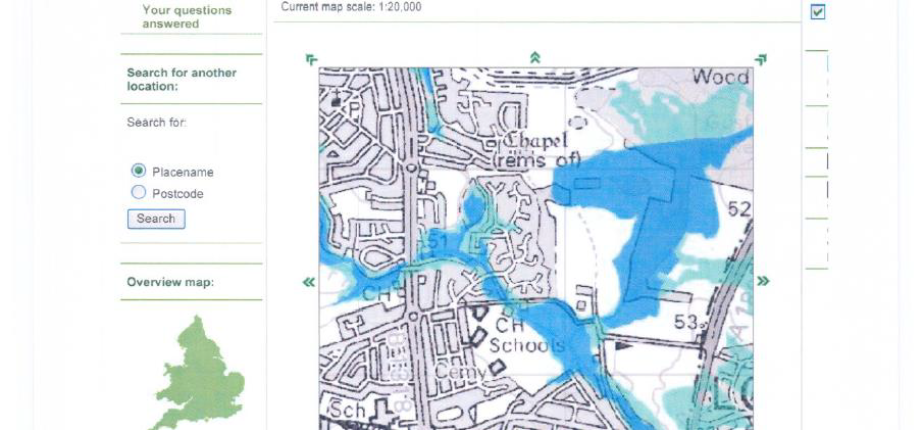
Using the Internet, I carry out post code searches on the Coal Authority Interactive website, Environment Agency website, DEFRA website, Radon Maps and old ordinance survey maps. This provides me with an indication of past Coal Mining in the area, mine entry locations, flood plain areas, land fill sites and any historic land use. The old ordinance survey maps also give an indication of mining shafts, old quarries, old woods or coppice, railway embankments and water courses.
When I initially take the instruction, I try to find out the approximate age of the property. This is not always possible as the purchaser often does not know, but with some research you should be able to determine the approximate age of properties in that area. It is very important to determine the age of a property as the construction techniques change from one period to another.
When we have determined the age of the subject property, we should have an understanding of the construction and therefore the likely defects that we will find. Even before we reach the property if we know it is, say, a 1930s semi detached house built in a suburban area of a city, we will know that we should expect a damp proof course, timber floors, ventilated sub floor void, generally inner leaf lintels of timber with the original heavy section timber window frames carrying outer leaf. When we survey the property we can compare the subject property to what we believed its original form would have taken.
Topography
As we approach to the subject property we should continually note the topography. This is the geographical term more commonly referred to as “lay of the land”, or the geographic characteristics of land in terms of elevation, slope and orientation. When we arrive at the property we must carry out a more detailed walk-over survey of the area, noting the fall in the land, whether there are any raised embankments or retained areas where fill material may have been imported to level the land. Are there any culverts close by or outlets into burns and rivers which would identify an earlier buried stream? I can name numerous occasions where a walk-over within 200 metres of a property I have been surveying has revealed outlets into local streams and rivers. Further research has then shown that these old water courses still exist in a pipe structure in close proximity to the subject property. When structural movement has then been identified, it is sometimes clear to see that the property is suffering from landslip into the ‘cut’. The topographical, “walk-over” survey, will also identify the location of trees and other vegetation which may be in a theoretic zone of influence to the property. Also, determine the exposure i.e. is the property in an elevated and exposed position or is it close to the sea and exposed to direct winds.
Exposure
The Beaufort wind scale is a good method for assessing exposure and defines such things as ‘Whole trees in motion, inconvenient to walk against wind’ as Force 7 ‘near gale’. This is essential in determining the property’s risk for storm damage or water penetration.
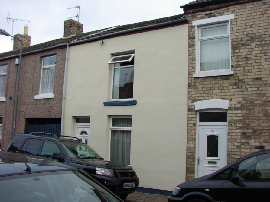
Surrounding Location
Where the property is located in a town, village or city, survey the street. Look at similar properties in the street and look for common indications of age and defects. For example, in Victorian properties there is often a rear offshoot. Is there a common vertical crack at the junction of the offshoot with the main building? In Victorian and 1930s properties there are often single storey bays. Is there common stepped brickwork cracking above the bay roof? When walking down the street, note if the properties have had wall tie replacement (identified by the drill holes through the brick on the exposed elevations). Have they had retro fix damp proof courses inserted (identified by horizontal line of drill holes above ground level, or the larger diameter Doulton type ceramic insertions or the electro osmosis terminal on the outer face)? How many of the roofs have been recovered, has the brickwork been re-pointed, have the windows been replaced? These are all indications of what has happened in the street and at what stage of deterioration there is in the properties of a similar age. Try to find an original unaltered building of the same style and age. I recall a survey I did on a late 1920s house in Gateshead. The building had significant defects which were difficult to identify. Eventually after a second walk around the estate I managed to find an original building and identified that a concrete staircase had originally been built on the outside of the building to give access to the flat roof. The removal of this staircase at some time had led to some of the cracking in the subject property. These stylistic clues are essential, and it is worth the time to look over the local environs.
Surrounding/adjacent properties
We have carried out our desktop study, we have taken in the local topography on our approach to the property, we have recorded notable landmarks, the presence of trees and vegetation and other land features. We need to identify the age of the property with a good degree of accuracy, we need to understand the construction details applied to buildings of these age and the common defects associated with this age of property. We then take a look at the streetscape, identify any properties of similar age and style and look for common defects in the properties in the street. We now narrow our survey down to the “block”. This “block” could be the external perimeter walls of a block of flats, the perimeter of a terraced row of houses, the perimeter of a semi-detached house or the “block” could be the perimeter of the individual detached building. The “block” could be a converted windmill, office block or other industrial or commercial premises
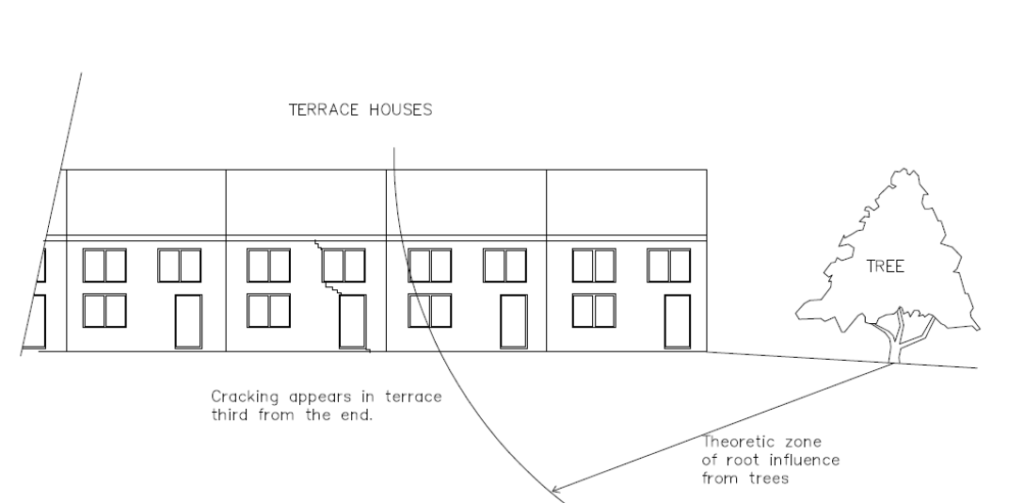
Even where the survey is concerned with a single unit in a block of 30 flats or the middle house in a terrace, it is imperative that we examine the “block” as a whole. On several occasions, I have surveyed a house third from the end in a terrace, which is suffering cracking. To find that the problem has been associated with a tree at the end of the terrace causing downward movement in the elongated “block”, the crack only becoming evident at the shear point in the foundations three houses down from the end of the terrace.
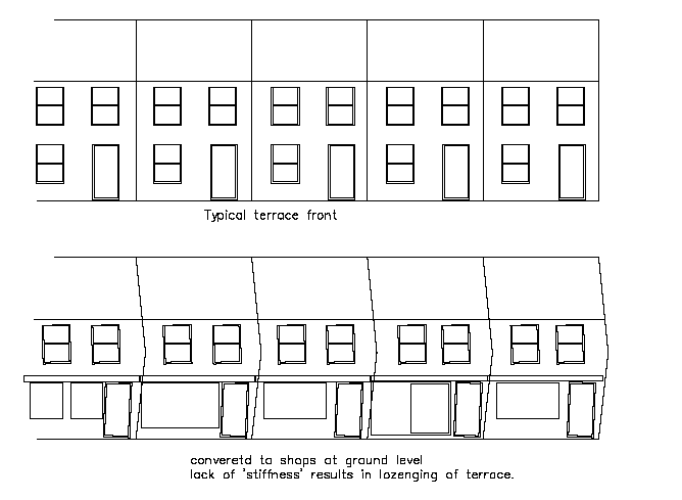
If we looked purely at that single unit the fault would never be identified. The terraced house on a steep bank side may show evidence of movement, which is associated with movement in the whole terrace due to slope instability. Again, looking at the specific property will not identify a current pattern of movement, which helps the surveyor identify the cause of the defect. Alterations in a “block” can significantly affect the whole of the terrace or “block”. Opening up of the shop fronts on the ground floor level of older premises can take away the stiffening properties of these infill walls and result in lozenging of the whole “block”.
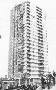
The disastrous Ronan Point, Canning Town explosion, where a 23-storey block built by Taylor Woodrow- Anglian from prefabricated concrete units that slotted together collapsed after a minor gas explosion in one of the flats. Having a catastrophic effect of the whole structure, like a pack of cards collapsing, killing five people in the process.. Poor design meant that huge stresses were placed on relatively weak sections of the block. A small jolt could topple the entire building. That was the end of this self-destructive building and changed the way we designed high rise structures, where each unit must be independent and not rely upon solely upon another. This information is essential in understanding how a Block performs and what defects can be expected.
Another example of how we must not look solely at the specific property but must consider the “block” as a whole. Cracking in the outer leaf of brickwork between ground and first floor windows in a long terrace could be caused by thermal expansion and contraction. The full length of the brickwork in the terrace or “block” will enable us to calculate the anticipated thermal movement in that total length of brickwork.
The Building under Survey
Things to consider before starting the survey
We have now narrowed our survey down to our specific building. It is important to “have a feel”, for the building. Approaching the property, you might notice a handrail or ramp to the front door. This gives an immediate indication that perhaps there was an elderly or disabled person living in the property. Internal decoration will also again often identify the occupant (who may no longer live in the property). The property may have locks on several of the bedroom doors, suggesting that the house has been used for multiple occupation perhaps by students. Does the property appear to have been well maintained, modernised, are there any improvements, alterations, extensions or changes in use?
A property deteriorates fairly quickly when it is left vacant or without due care and attention.
A neglected property often needs special attention and a little more vigilance than a well kept, modernised and loved home. On the other hand, is the property owner trying to cover up some significant defects. For example, are the internal faces of external walls clad with plasterboard, hardboard or timber cladding? Is this cladding purely for decorative purposes or is it hiding severe dampness? Are the walls or ceilings papered with a heavy embossed wallpaper or heavy patterned artex coating?
These are often clear signs that the property has undergone some sort of structural movement that the owner does not want identified. Has the original outer face of the brickwork been rendered and pebble dashed? Is this hiding significant cracks and ‘out of level’ brickwork lines or has it been rendered because there are 225 mm thick solid walls suffering water penetration?
Beginning the survey
Working anti-clockwise round the building, I end up back at the front right corner. Internally I always start on the ground floor right corner, proceed to the upper floors and I finish with the dirtiest part of the survey, the roof void.
It is essential to review your external notes when discovering any defects internally. For instance, externally you have noticed a shared chimney to the main house at a roof verge and on the party wall. Your internal inspection reveals fireplaces in the lounge, dining room and two upper bedrooms. Your external notes also identified a single chimney stack to the rear offshoot. It is very easy not to notice that the smaller fireplace that was originally in the offshoot kitchen has been removed. It is no longer supported at either first floor level or at ceiling level and the chimney is corbelled out of the brickwork in the roof space.
You may have noticed a stepped or vertical crack in the front elevation wall between the lounge and bedroom windows. However, when you examine the wall internally there is no evidence of this crack. Has this crack been filled and decorated over or is the cracking caused by nothing more sinister than thermal expansion and contraction, which has not affected the inner leaf?
Or, on the other hand, you may have noticed a slight crack in the rear corner of the house and when you look into the rear corner bedroom of the house you find a very significant crack in the plasterwork. Referencing your notes when on site will help you to reach a hypothesis on the cause of the crack.
Similarly, where you have noticed leaking gutters, missing roof tiles or slates or water staining on the external elevations, this should help you to direct a more thorough internal inspection for dampness and timber decay.
We started our survey with a desktop study, facts and information sourcing, a visual inspection while approaching the property, a walk-over survey of the site, examination of the local environment, determining the age and construction of the building and then commencing the methodical survey on the building, outbuildings and boundary walls. The whole purpose of the survey, let us not forget, is to find defects, identify the cause of the defects and recommend remedial works. Our thorough external and internal survey, the site notes, photographic evidence and surveying equipment and instruments will help us locate defects or at least prepare us for where possible hidden defects may be found. It could also identify locations and sources where there may be future problems or maintenance implications. To reach a logical conclusion, the surveyor will need to choose the appropriate methodology.
Survey Methodology
During the survey there are two types of logic that can be used: inductive and deductive logic.
Inductive inference
Inductive inferences relate to observations about the actual building or premises and generally arrive at a conclusion. For example, if when entering the building we step onto the carpet covered floor and the floor drops by 50 mm. You walk further into the building without the floor dropping until you come again to the external elevation and the floor again sinks 50 or 70 mm; one can logically conclude that the sinking of the floor is caused by rot or failure of the joist ends. That is inductive reasoning from particular experiences.
Deductive inference
Deductive inferences start with general knowledge and predict a specific observation. For example, if a building was built post 1985 under the concept of approved documents, then we can logically infer that the property will contain a damp proof course, cavity wall construction, inner and outer leaf, lintel support and foundations to a depth expected in the approved documents. Therefore, if, for instance, we found evidence of dampness in the wall we can deduce that it will not be due to the absence of a damp proof course.
Similarly, we know that early wall ties were not galvanised and from about 1930 wall ties were galvanised which give them a better protection, but even this was considered substandard by today’s standards. In 1981 the standard of protection to wall ties was improved. By deduction, we can assume that horizontal cracks in the bed joints of brickwork in houses built post 1981 would not be caused by wall tie corrosion. That is deduction.
Solution to complicated problems must be approached with a mixture of inductive and deductive inferences, that weave back and forth between the observed building and the mental hierarchy of our knowledge of construction techniques.
The system of surveying, the note taking, further investigations and research is a system of formalised scientific method. By applying formal scientific method to a fairly simple construction – a house – there should be no defect that cannot be diagnosed.
To apply the formal scientific method, everything must be recorded, so that you know at all times where you are, where you have been, where you are going and where you want to get. This avoids confusion. Using inductive and deductive inferences, the surveyor arrives at a hypothesis and puts in place experiments for a scientific analysis of the hypothesis. Sometimes the act of writing down your findings helps you to find your direction. Some of the experiments disprove the theory.
The logical statements entered into the note book are broken down into eight categories:
- A statement of the problem.
- The hypothesis as to the cause of the problem.
- Experiments designed to test each hypothesis.
- The predicted results of the experiments.
- The observed results of the experiments.
- Conclusion from the results of the experiments.
- Comparison with the original hypothesis.
- Review and reassess.
CASE STUDY
The following case study is a worked example of how deductive inferences can help solve defects diagnosis. The case study is in Blue text to define if from theory.
Introduction
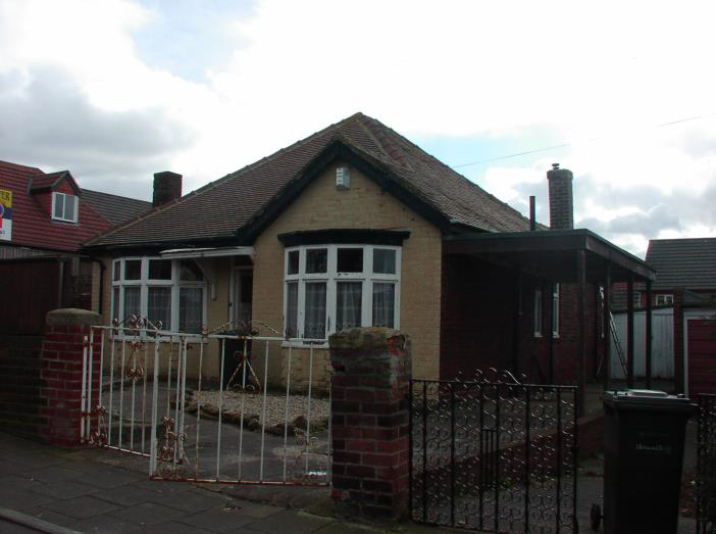
The client was a Local Authority Housing Department. The Council had around 8,000 properties, built between 1920 and 1980. The tenant had recently moved into the property and was carrying out full redecoration. The tenant had reported cracking in the party wall and front wall of her bungalow, only identified when wallpaper had been removed.
Desktop study
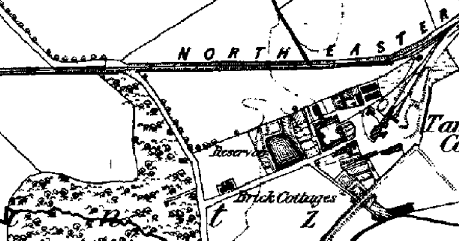
A desktop study showed that the bungalows were built very close to an old railway embankment, the railway had been used to carry coal from the nearby colliery with a reservoir nearby. Old ordinance survey maps also showed that there had been an old gravel quarry opposite the location of the bungalows. Current ordinance survey maps showed an open greenfield site in front of the bungalows, which faced east.
The client records advised that the bungalows had been built in 1965.
Local environment
The approach revealed an estate of about 200 council properties with 16 bungalows on the perimeter of the estate. The bungalows were in an exposed position facing onto open fields. The bungalows were at the bottom of a gently sloping site.
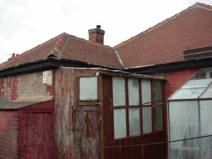
Property description
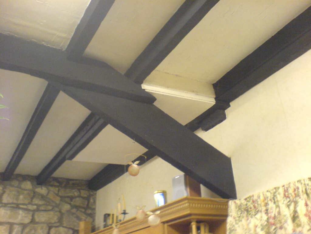
The construction of the bungalow comprised cavity brick wall construction, with a bitumen impregnated hessian damp proof course 225 mm above ground level inner leaf concrete lintels, whilst the outer leaf brickwork above window and door openings comprised a 225 mm soldier course bearing directly onto the timber frames. The roof structure comprised 2 nr kingpost roof trusses, 65 mm x 185 mm purlins spanning between party walls and trusses. In turn, the timber purlins carried 50 mm x 75 mm common rafters at 450 mm centres. The rafters were bearing onto the wall plate on the inner leaf blockwork. Party walls between the bungalows were cavity brick construction. The roof was clad with concrete interlocking tiles over bitumen sarking felt.
The survey
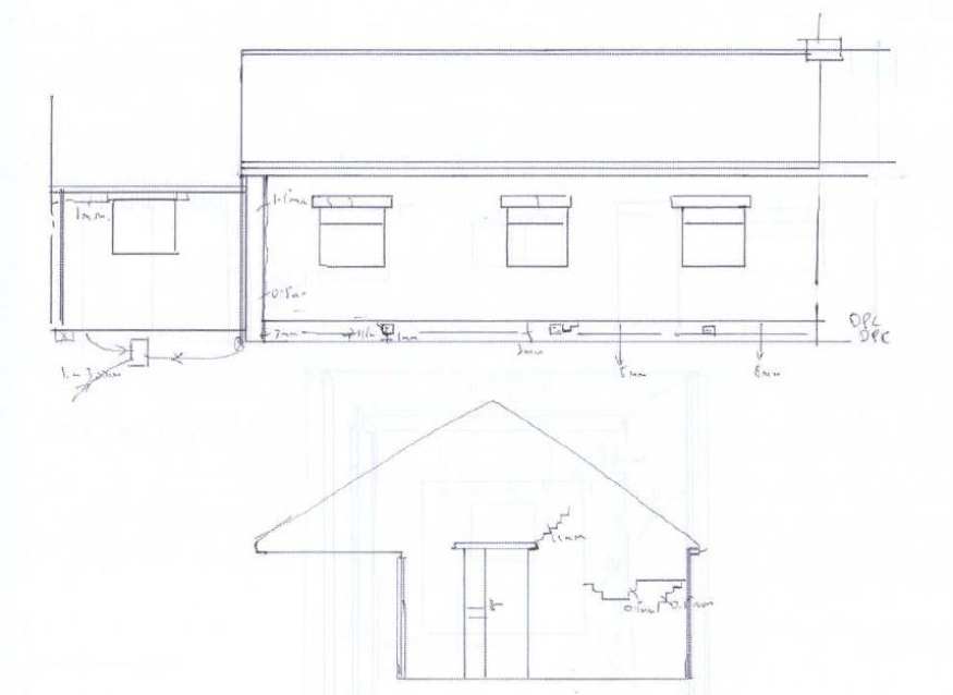
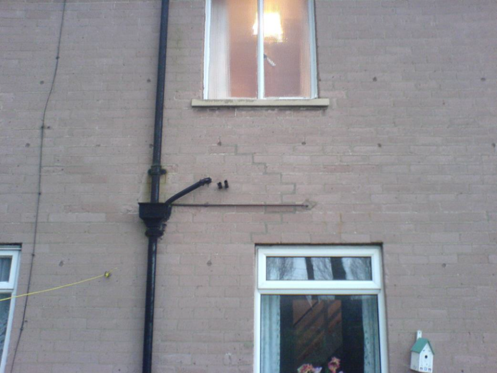
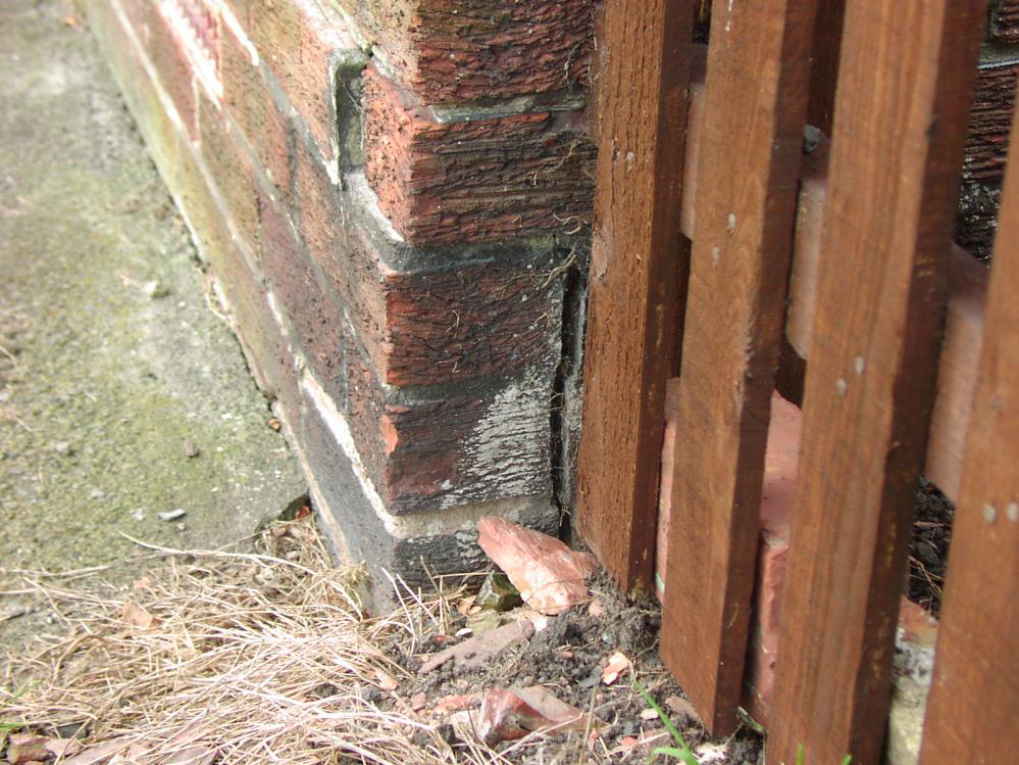
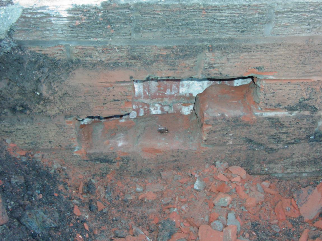
The subject bungalow was mid terrace and the block comprised of 5 nr bungalows. Examining the external elevations of the block, as a whole, cracks were recorded of between 1 mm and 18 mm wide. The 18 mm wide cracks were at the north east and south east corners of the bungalows below damp proof course level. Displacement at damp proof course level of up to 20 mm was also recorded. The 1 mm wide cracks were mostly on the rear elevation at the junction with the small offshoot.
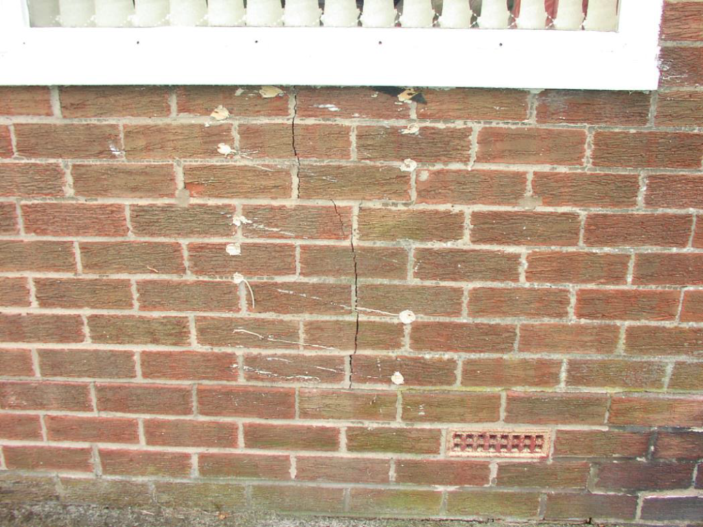
In the subject property, mid terrace, there were 8-10 mm wide cracks running from damp proof course level up to the lounge window cill.
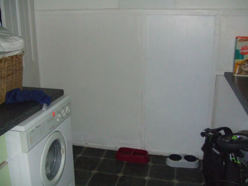
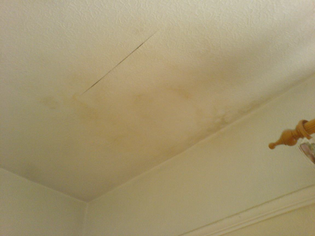
Internally, by photographs and sketches, the following cracks were recorded; a 12 mm wide crack in the party wall close to the north east corner of the bungalow and an 8 mm wide crack in the front wall of the bungalow beneath the lounge window. A displacement was also noted between the suspended timber floor and the skirting boards along the front elevation. The south east corner bedroom (front elevation) was covered with a heavy wallpaper. However, by simply drawing hands over the wall a crack could be felt in the party wall close to the south east corner. Applying a spirit level to the front elevation wall revealed a 20 mm inward lean of the wall at floor level. There was other minor cracking in the property but nothing significant. A floor plan was sketched of the bungalow and recorded all areas of movement.
Intrusive investigation
We obtained permission from the Council and the tenant and lifted a floorboard in the front entrance lobby. This revealed a 250 mm deep sub floor void and a concrete oversite. There was no evidence of “heave” or cracking in the oversite concrete.
Deductive and inductive inferences
The direction and mode of cracking suggested lateral movement of the front elevation wall below damp proof course level. The displacement at the damp proof course also indicated lateral movement.
Statement of the Problem
Our statement of the problem is simply cracking in the party wall and front wall of the bungalow. Classified by BRE Digest 251 as Category 3 “Moderate Damage”. There was evidence of foundation movement and the BRE Digest recommends further investigations and some rebuilding may be required. The statement also recognised that the property be deemed “unfit” under the Housing Act due to structural instability and would not meet “Decent Homes” legislation. It was imperative that we identified exactly the cause of cracking and the most cost effective method to rectify the problem as all 16 bungalows were suffering similar ‘casualty’.
Hypothesis
After reviewing our notes and sketches and with our knowledge of local construction methods in the period 1960 to 1972, our hypothesis as to the cause of the problem was that the property was suffering from sulphate attack on the concrete sub floor void.
In the North East, during the period 1960 to 1972, there was a readily available and cheap sub base available to contractors. The sub base was colliery waste and burnt shale from coal power stations. This was used readily by our client during the building boom years and with the close locality of the colliery and ash railway embankment there would have been a readily available source. When moisture is present in the shale or ash, the sulphates are taken into solution and migrate to the interface of the surface of the shale and the underside of the concrete slab. It is common for there to be no damp proof membrane between the shale and oversite concrete. The dissolved sulphates react with the constituents of Portland cement, initially resulting in significant expansion of the concrete. The rate of the reaction and the extent of damage will be dependent upon the amount of water present, the depth of fill, the quality of the concrete, heat sources and the effectiveness of any separating membrane.
Generally, the deeper the fill the greater the quantity of sulphates that will be available whilst the higher moisture content the more readily will the sulphates migrate through the fill. The subsequent expansion of the concrete will often push the external walls outward causing displacement at damp proof course and cracking at the corners of buildings.
In this respect, the direction and mode of cracking, the fall of the land suggesting that there will be deeper fill at the front of the house and again the direction of fall of the land would direct any ground moisture towards the front elevation of the bungalow. Therefore, I made my hypothesis as to the cause of the problem to be sulphate expansion of the concrete oversite.
Experiments to prove or disprove the Hypothesis
To prove, or as importantly, to disprove the hypothesis, we carried out further investigations in all of the bungalows on the estate, some nearby houses and organised for a core sample to be taken through the concrete oversite and samples of the filling material be taken for analysis.
The concrete sample and fill samples were sent off to a local analyst and we requested tests on the samples for sulphate transference to the concrete at its interface with the fill, the sulphate content of the remaining fill and moisture content. The experiment by drilling the core hole through the slab also revealed that there was no damp-proof membrane between the fill and the interface of the ground floor slab. The core hole also identified that there were no pockets of standing water and the hole remained dry throughout. If there had been standing water this could have been recovered and again analysed for detergents etc, to determine whether the water was naturally occurring ground waters or foul waters from, say, a leaking drain or if it contained fluorides from a leaking water pipe.
Our predicted result of the experiment was that the filling material would be a Class 3 or above in accordance with the BRE Digest 250 superseded by BRE Digest 363 ‘Sulphate and acid resistance of concrete in the ground’ and that document was superseded by BRE Special Digest 1, that there would be transference of sulphate to the filling material. We also expected moisture contents to be higher at the front of the property where in fact the fill was up to 700 mm deep than they would be at the rear of the bungalow where the filling material was limited to 200 mm deep.
When the analysis results returned, they showed a Class 1 to Class 2 sulphate in the fill and no transference to the oversite concrete.
Review of Hypothesis
We concluded from the results of the experiments that the cracking and the displacement at damp proof course level was not caused by sulphate expansion of the concrete oversite.
Although the experiment did not prove my hypothesis, it was nevertheless successful. It proved that the defect was not caused by sulphate expansion.
We reviewed my written findings and prepared a cause and effect analysis to solve the problem.
Cause and effect relationship
All too often a defect, is not considered, until it is first encountered. For instance, during a property survey a crack is found in an internal wall. Only when this “effect” or ‘Casualty’ is observed will the cause considered. Using deductive inference we should have been expecting the defect before we reach the casualty and a hypothesis can be made.
To reappraise the methodical survey process. The hypothesis based on deductive inferences was tested against experiments to prove or disprove the hypothesis. These experiments disproved the hypothesis of sulphate attack. After appraising the results and reviewing the findings, we set up cause and effect analysis.
The cause and effect analysis arrange hypothesis and possible causes of the damage into a written process by listing all of the possible causes and possible effects. Cause and effect analysis do present a large amount of information by showing links between events and their potential or actual causes and provide a means of generating ideas about why the problem is occurring and possible effects of that cause.
Initially, start with a concept map. Central to the map is the title of the subject. This is shown in the diagram marked Figure 1. From this subject take a line diagram out from the circle and labelled it with possible hypotheses. These are shown by the lines marked 2 in Figure 1. The lines marked 3 belong to the additional level of information with sub-headings.
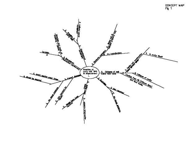
From this concept map, we listed 7 hypotheses of the possible cause. Having already ruled out the hypothesis of sulphate expansion. Using historic data held by the Local Authority we ruled out the possibility of explosion as a hypothesis and because of the improbability we also ruled out internal impact damage as a possible hypothesis. This left me with 4 remaining hypotheses:
- Subsidence,
- Hygro-thermal movement,
- Initial building defect,
- The collapse of the wall below ground level.
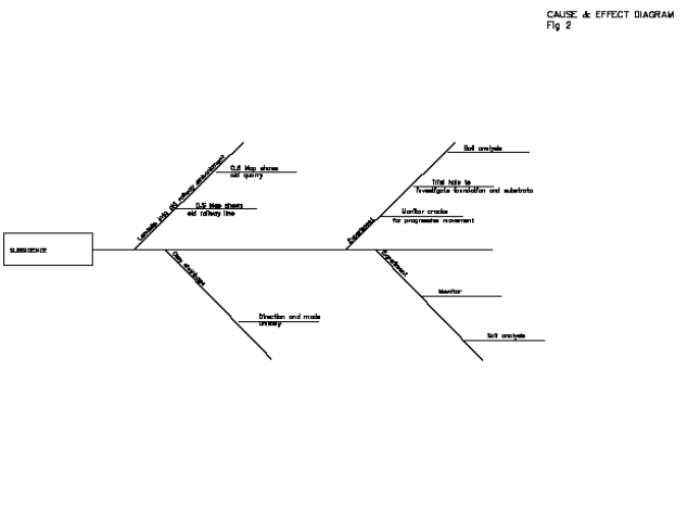
For each of these hypotheses, we set up a cause and effect diagram showing in Figures 2, 3 and 4.
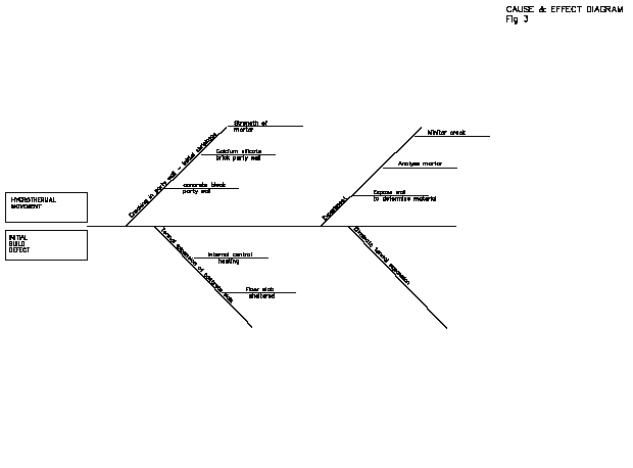
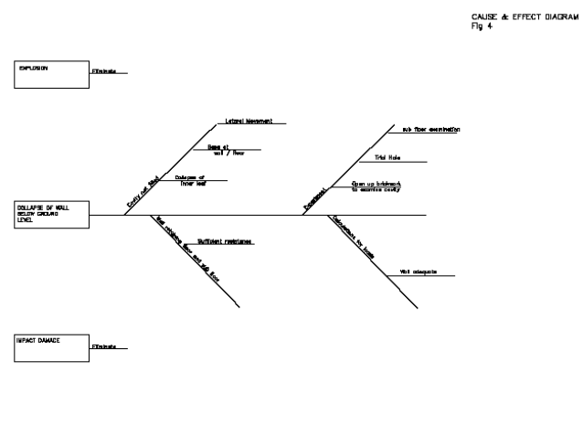
In Figure 3, the hygro-thermal movement and initial build defect is combined as one hypothesis. This was done for ease of experiment as to prove or disprove either of these hypotheses the same experiment would have to be used. Using the cause and effect diagrams, we set out the cause and effect list, as shown below.
Hypothesis 1 Subsidence
| Cause | Effect |
|---|---|
| Landslip | Cracking at junction of front wall with inner walls. |
| Lateral movement. | |
| Progressive opening of crack. | |
| Clay shrinkage | Cracking at Junction of front wall with inner wall |
| – if foundation depths vary. | |
| -exacerbated by trees and vegetation with root affecting zone of influence. | |
| -cracks would fluctuate opening in summer and closing during wet periods. |
Hypothesis 2 Hygrothermal movement
| Cause | Effect |
|---|---|
| Initial shrinkage | Common with Calcium Silicate bricks and concrete blocks. |
| – initial movement only and not progressive. | |
| – Historic within few months of construction. | |
| Thermal expansion and contraction | Requires significant changes in temperature or humidity. |
Hypothesis 3 Defects built in at construction
| Cause | Effect |
|---|---|
| Defects built in at construction | Historic, other than minor movement at shear crack. |
| Would be non-progressive. |
Hypothesis 4 Collapse of wall below ground level.
| Cause | Effect |
|---|---|
| Collapse of wall below ground level. | Loading on wall from 750mm deep fill, concrete slab, sleeper walls and floor loads. |
| Passive resistance equal to infill. | |
| Collapse of cavity and inner leaf. |
The process of experiments to prove or disprove the new hypothesis commenced.
Further investigation
Trial holes were excavated at the front and rear of the subject property to 1.5 metres below ground level adjacent to the front and rear walls of the bungalow. We recovered soil samples and took sketches and photographs at foundation depth and recorded visual evidence of the substrata.
The front elevation foundation was 1100mm below ground level bearing onto a sandy clay subsoil. The foundation comprised a 225 mm thick concrete strip foundation projecting 100 mm from the front face of the outer leaf brickwork.
At the rear, the foundations were 600 mm below ground level. The foundations comprised a 225 mm thick concrete strip foundation projecting 125 mm from the outer face brickwork. The foundations were bearing onto a sandy clay subsoil.
Both trial holes remained dry throughout the excavation. Backfill material between the foundation and ground level comprised builder’s rubble and soil.
Internally, floorboards were lifted adjacent to the front elevation wall. This revealed that the sub-floor concrete was not directly abutting the front elevation wall and there was a 15-20 mm gap.
Plaster was removed from the internal face of the party wall and front elevation wall. The opening up work revealed that the party walls were built with a “common” clay brick with a 50mm cavity between two leafs. The brickwork appeared to be bonded to the front wall of the house with stretchers at every fifth course. Bricks were removed from the front wall approximately 450 mm below concrete sub-floor level. The brickwork below ground level was bowed by approximately 20 mm. There was no cavity infill below ground level and no evidence of wall ties in the brickwork below ground level. The below ground brick wall cavity was reduced from a 50mm gap to 15 mm width.
Monitoring stations using metal disc studs and Vernier callipers were set up on the cracks at the internal wall junction.
It was noted in the experiment that there were no tree roots or any vegetable matter in the trial hole excavations at any depth. Soil samples at 1.5 metres below ground level were taken for analysis. The results from the analysis showed a sandy clay, which had a plasticity index of 17, classifying the clay as a low shrinkability clay, as defined by NHBC Chapter 4. This clay had a plastic limit of 19% and a liquid limit of 36%. The moisture content in the clay was 24%.
The natural clay substrata does fall from the rear to the front of the bungalow. Therefore, the filling material beneath the concrete sub-floor is deeper at the front elevations of the bungalow. The concrete strip foundation was laid directly onto the clay subsoil and there did appear to be enough resistance to lateral movement. At 1100 mm below ground level and with no evidence of tree roots within the clay subsoil, it is unlikely that the low plasticity clay would be affected by moisture variations in the subsoil.
There was no evidence that the party wall was suffering from initial shrinkage or expansion of the clay brickwork, and there was no reason to expect extremes of temperature variations, which would cause thermal expansion and contraction. Although the party wall was only sporadically tied into the inner leaf of the front wall, there was no visual evidence to suggest that a crack existed shortly after construction or that the outer leaf brickwork had been built out of plumb.
The further investigations and experiments did show that the cavity of the front wall below ground level had not been filled.
Observations
The pressure exerted from the deep fill material at the front wall of the house had been retained by the inner leaf of the front elevation brickwork. As the brickwork mortar has deteriorated, possibly exacerbated by chemical attack from the low sulphate content in the fill material, the inner leaf has been pushed laterally into the cavity. This caused the stretchers tying the party wall and the front wall together to shear and a crack to form at the junction of the front wall and inner party wall. This also created a gap between the concrete sub-floor and between the timber floorboards and skirting boards. The cavity has closed to such an extent that because of slovens in the cavity the inner leaf began to press against the outer leaf and cause subsequent outward lateral movement of the external facing brickwork.
Conclusion
Following the investigations, the conclusion was, that the cause of the cracking and displacement in the bungalow was the collapse of the below ground inner leaf brickwork.
Our recommendations to the Local Housing Authority were to lift all the floors of the bungalows, excavate the concrete sub-floor, take out all of the fill material, re-build the inner leaf brickwork of the bungalow and infill the cavity with concrete.
The client, however, had a limited budget and the estimated cost of £18,000 per bungalow to rectify the defect, could not be justified. We were asked to comment on how progressive the movement was, how much it would affect the stability of the properties and whether the properties were still fit for habitation. It was the Client’s opinion that it may be more economical to demolish the bungalows than to repair. If we could justify that the bungalows would remain stable and meet the Decent Homes Standards, including HHSRS (Housing, Health and Safety Rating Scheme) then only temporary repairs would be carried out and the tenants would continue their tenancies.
It is interesting to see that we appear to have correctly identified the cause of movement. What has changed since our first involvement is the effect and Proximate Cause. The effect originally was cracking in the party wall and displacement at the damp proof course level. The Local Authority has their own agenda and the ‘effect’ now could be demolition.
Remedial action
We have attempted a method of filling the cavities with a high flow concrete mix in an attempt to maintain stability.
Proximate cause
The most common legal definition of ‘Proximate Cause’ is contained within the case Pawsey v Scottish Union & National (1908):
“Proximate cause means the active, efficient motion that sets in motion a train of events, which brings about a result, without the intervention of any force started and working actively from a new and independent source.”
Proximate cause is the dominant cause. It does not have to be the first.
Insurance terminology, when investigating claims works on the philosophy of proximate cause. Where every event has a cause and cannot be treated as isolated. It will have been lead up to by a succession of occurrences or causes and the insurable event is nothing more than the last link in the chain of causes and effects. For insurance purposes, the principle of proximate cause means identifying the action that lead to the probable cause of a particular event, leading to a loss and whether this event is insured. The last event is usually that which activates the claim. However earlier and any intermediate events and causes, which happen, are more difficult to identify.
As described before in the above case study, the event chain must be carefully considered at each stage, questions as to whether that particular chain was broken by a new and intervening cause, using deductive inferences.
Remote causes are original actions which started the motion towards loss, when another new and independent cause occurs and the loss happens. Usually a period of time elapses between the original cause and the remote cause. The case of Roth v South Easthope Farmers’ Mutual Insurance Co. (1918) where lightning damaged a building and weakened a wall and soon afterwards, the weakened wall was blown down by high winds. It was considered that the lightning was the proximate cause.
Also, in Gasgarth v Law Union Insurance Co. (1876) fire damaged a wall and weakened it. Several days later a gale blew down the weakened wall. It was held that fire was NOT the proximate cause.
These cases illustrate who the first action or event is a remote cause or can it be considered as the proximate cause of a loss.
Bibliography
- RICS professional standards and guidance, UK Home survey standard 1st edition, Nov 2019
- Judge Phillips, in Cross v Mortimer
- The Beaufort wind scale
- https://plato.stanford.edu/entries/logic-inductive
- Clive Richardson AJ Database CI/SfB (A3a) www.gov.uk › Housing, local and community › Housing health and safety rating system (HHSRS) guidance www.communities-ni.gov.uk › decent-homes-standard BRE Digest 251
- BRE Digest 250 superseded by BRE Digest 363 ‘Sulphate and acid resistance of concrete in the ground’
- BRE Special Digest 1
- NHBC Chapter 4 www.iedunote.com › proximate-cause
- Pawsey v Scottish Union & National (1908)
- Roth v South Easthope Farmers’ Mutual Insurance Co. (1918)
- Gasgarth v Law Union Insurance Co. (1876)